What is a PID Controller?
Profire’s PID temperature controllers are an important component to the overall functionality of our complete burner management systems. The PID (Proportional, Integral, Derivative) controller provides regulation of setpoints in temperature-related systems and other processes. Characteristics of the specific application’s process flow, fuel pressure, and valve response times all contribute to the response of a PID control loop and vary from appliance to appliance. Specifically in our products, it is used to maintain control of process temperatures by adjusting the signal of a control valve which can include proportional, linear, or quick opening to regulate the flow of fuel to a burner.
How does a PID controller work?
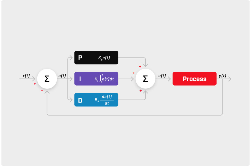
When we look at a PID controller and how it works, it can seem complicated. To put it simply, the PID controller responds in proportion to the process changes of an industrial system. A control loop is established where temperatures are compared to a desired setpoint to get an error value. The PID algorithm interprets the size, duration, and rate of change of the error and determines an appropriate controller output to achieve the predetermined process setpoint. This is referred to as the proportional gain or proportional band.
Proportional Band
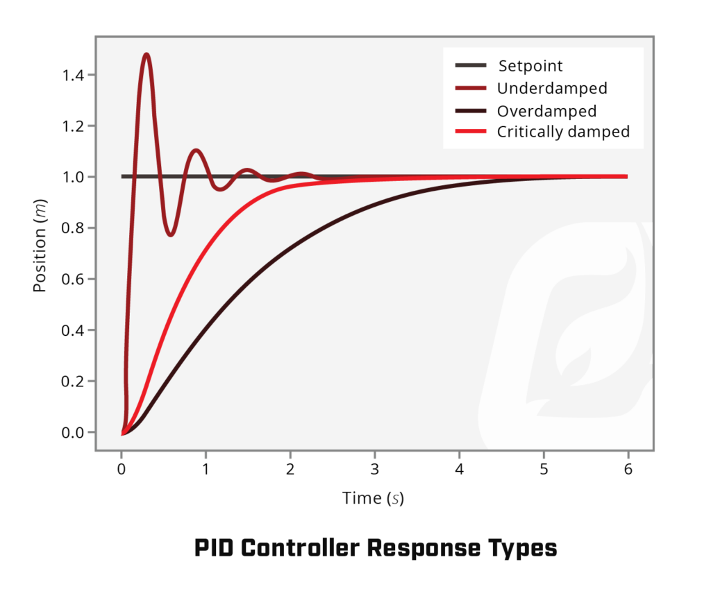
The proportional gain is a result determined through a calculation of the controller’s present error, setpoint value, and present process variable. In relation to a proportional band, it is the calculation that provides the range of how you can affect the controlled variable within the operating range of 0% to 100% of the controller. The band setting also affects the speed at which your system reacts to changes in temperature and is completely dependent on the specific application it’s being used with. For instance: a large heater with an undersized burner may only need a proportional band of +2°C or +3°C because even at 100% output, the temperature control valve (TCV) will have a difficult time heating the process fluid to its setpoint. Clamping at 100% until very close to the setpoint will not be an issue. On the other hand, if the burner is oversized and is heating something with a low heat capacity (i.e. air), the proportional band may need to be +20°C or +30°C to avoid excessive overshoot. These values are described as either an under-, an over-, or a critically-damped system. Damped refers to how quickly a system returns to its original state following its response to change. Let’s take a look at each response:
- Under-Damped System – A smaller proportional band increases gain, therefore, a small change in temperature will yield a large response in output. As the proportional band decreases, the system becomes under-damped. This means that the temperature will oscillate and will swing above and below the setpoint. A very low proportional band will cause the system to behave similarly to an on/off control setup without a proportional valve. A properly tuned under-damped system will result in 1/4 amplitude decay. That means the overshoot is 1/4 of the size of the overshoot before it. After 4-5 overshoots you should be close enough to setpoint to call it good.
- Over-Damped System – A larger proportional band decreases gain, therefore, a large change in temperature will yield a smaller response in output. As the proportional band increases, the system becomes over-damped. This means that the temperature returns to the setpoint without oscillating. However, if it is too large, it will return to the setpoint slowly and will be sluggish to react to changes in temperature. The output is limited to the range of the minimum temperature control valve (TCV) opening and the system’s 100% response.
- Critically-Damped System – This response is generally the desired response for your system as it has the fastest achievable response time with minimal overshooting.
Credit to: Introduction to PID — FIRST Robotics Competition documentation (wpilib.org)
What is integral time?
The integral time or response refers to how the system accelerates the movement of the process temperature towards the setpoint and eliminates the residual steady-state error that occurs with a proportional controller. The larger the input error (error = setpoint – temperature) the greater the effect of the integral term. Our products express integral time as minutes per repeat. The smaller the integral time, the quicker the system will increase the output. The larger the integral time, the slower the system will increase the output. Other control systems may represent integral time as repeats per minute, which would mean a smaller number would generate a slower response.
What is derivative time (Pre-Act)?
The derivative time or response refers to the allowance for a PID controller to predict future errors by calculating derivatives of the error or input. PF3100 PID controllers take the derivative of the input measurement rather than the error. This means that the controller is looking at the rate of change of the error and moving the controller in accordance with what it thinks the error will be after the derivative time. This is a standard PID feature that prevents large output swings when the setpoint is changed. When the setpoint increases, the error term increases instantaneously. If the derivative of the error term was used for the derivative term, the output would spike in response to the setpoint change, even though the state of the system didn’t really change. Derivative action is seldom used in practice because of its variable impact on system stability in real-world applications.
Increasing the derivative time increases the output contribution.
Decreasing the derivative time decreases the output contribution.
Cascading more than one PID
The benefit of using a Profire controller, including the PF3100 Series, and PF2200 Series, is that they have been purpose-built with the ability to cascade PID controllers using multiple thermocouples. An example of how we could commission it in the field is to have the outer controller configured to control the temperature of the fluid using a thermocouple located a distance from the heater. Instead of controlling the heater directly, the output of the outer PID controller sets the setpoint for the inner PID. The inner PID controller controls the temperature of the heater using a thermocouple attached to the heater. The inner controller’s error term is the difference between this heater temperature setpoint and the measured temperature of the heater. Its output controls the actual heater to stay near this setpoint. The proportional, integral, and differential terms of the two controllers will be different. The temperature of the outer loop will change more quickly than the inner loop since the inner has more volume to heat. By cascading the PIDs we allow the inner loop to respond to the change in the outer before the change is realized in the inner loop.
For more information on PID Controllers and how we can implement them in your customized solution please contact us.